Electrolytic capacitors
A beginner's guide
Scope
This article is mainly aimed at people who want to repair or restore tube equipment, but have no formal education in electronics as such or more specifically in high voltage power supplies. The article endeavours to give you a basic knowledge the inner workings and practical use of one of the sensitive components in such equipment, the electrolytic capacitor.
Capacitors
To understand the electrolytic capacitor, we must first look at capacitors in general. The usual scematic symbol for a capacitor looks like this:
![]()
And it really describes the component well. A capacitor is basically two conductive plates separated by an isolating layer. The isolating layer, which is called the dielectric can be many different materials, and has great influence on the characteristics of the capacitor, but more about this later.
Let's assume we apply a voltage to a capacitor:
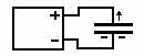
As voltage is applied, electrons flow from the negative side of the voltage source and into one plate. Electrons repel other electrons, so the surplus of electrons on the plate connected to the negative supply will repel the electrons on the other plate. These electrons flow away into the positive supply terminal. A current is flowing. After a time interval, the power supply in not able to crowd more electrons together on the negative plate (voltage is really a measure of how hard your supply can stuff electrons together), so the current peters out and stops. We now say that the capacitor is charged; there is a surplus of electrons on one plate, and a corresponding lack of electrons on the other.
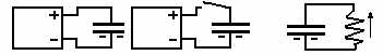
Next, we could disconnect the capacitor. The charge will stay on it. If we connect a load circuit over it, the electrons start flowing from the crowded (negative) plate to the empty (positive) plate; a current flows. When an equal level of electrons on both plates is reached, the current stops. We say that the capacitor is discharged.
Now, that is cool, but what can we use this thing for?
Well, we now have a component that can store a charge, and that will allow an alternating current to pass, but not a direct current. This can be used in:
The electrical value (capacity) of capacitors is measured in Farads. One Farad (F) is a capacitor that reaches a charge voltage of one Volt when charged with a current of one Ampére for one second. This is a nice unit that goes well together with other electrical units. Unfortunately, it is also an extremely large unit. Rather like if our basic measure of distance was equal to the cross section of the Solar System! Therefore we need to use various fractions of the value. Actually, the largest unit we normally use is the Microfarad. Below is a list of the normally used units:
| Unit | US abbreviation | Euro abbreviation | Size |
| Microfarad | MF | µF | 0.000001F |
| Nanofarad | - | nF | 0.000000001F |
| Picofarad | MMF | pF | 0.000000000001F |
Quite a range! So what is determining the value of a capacitor? Well, all else alike, the capacity is proportional to the area of the plates, but the distance between the plates is important too; the closer the plates, the higher the capacity. The type of dielectric (the isolating layer, remember?) has a lot to say too. Now, I have already mentioned that electrolytic capacitors have their main use in filtering, and in that business size counts. Filter capacitors come in sizes from tens to hundreds of MF (for low voltage power supplies, thousands of MF).
So, how to build a large capacitor?
One way to make a large capacitor is to take two long strips of aluminium foil (=large plates), put strips of isolating materials between them, and make a nice compact roll. Capacitors up to around 1MF can be made this way, but they are physically big, so if we want even higher capacity, we need to look for other things than plate area. It happens that we know of a very thin and very voltage resistant type of isolation material: Aluminium oxide. If we cover a strip of aluminium foil with a thin oxide layer, we have one plate and a very thin dielectric. Problem now is to make the other plate come close enough to the other side of the oxide layer. The thing that comes really close to anything is a liquid, so if we submerge our oxide covered plate in a conducting liquid, the liquid forms the other plate, and we can make a very large capacitor. A conducting liquid is called an electrolyte, see?
But there are problems
Nothing comes for free, so this type of capacitor has its drawbacks. Some have practical solutions: Instead of having liquid sloshing around inside the capacitor, an electrolyte-soaked paper is used, some modern types are even virtually solid. Others become restraints we have to live with:
The oxide layer is made by an electrolytic process; the foil is submerged in some liquid and current is passed through the liquid into the metal, forming the oxide layer. This is an advantage and a disadvantage: The good news is that the dielectric layer has self-healing capabilities, so if a weak spot occurs, the resulting leakage current will more or less rebuild the isolation. This is the reason electrolytic capacitors can regenerate if you raise the voltage over them slowly. The bad news is that the process is reversible! If you reverse the polarity, even the slightest leakage will begin to tear the dielectric down, resulting in more leakage, which tears away more dielectric, which ---- well, you get the picture. This is the reason you need to observe polarity strictly when using electrolytic capacitors.
Another problem is the presense of the electrolyte itself: Exess heat, either from inside or outside sources, will eventually start to evaporate the liquid, building up pressure, which may very well result in a violent leak, even an explosion. And as if that was not bad enough, once the elektrolyte escapes, it will interact corrosively with other parts of the equipment, because all electrolytic liquids are more or less corrosive.
Finally, even if our electrolytic capacitor escapes a violent demise, its very construction gives it a limited life-span. Given time, the dielectric may deteriorate beyond regeneration, resulting in a high leakage current, or the electrolyte will eventually dry away, reducing the capacity by several orders of magnitude. This is the reason that people who restore antique radios will often be faced with the need to replace electrolytic capacitors.
Three sure ways to kill an electrolytic capacitor:
The rules for a long peaceful life are, of course, the opposite. When replacing electrolytic capacitors in old equipment, never, never go below the voltage rating of the original parts. Modern componets are usually more compact, so if you cannot get the exact rating, choose a higher one, there will usually be room for it. If wrong polarization or overvoltage has caused an electrolytic capacitor to become hot, discard it. Look out for heat sources; in old power supplies, there is often a large hot drop resistor placed near the filter capacitor, make sure it doesnt transfer too much heat to the capacitor.
Chosing value and rating when replacing elctrolytic capacitors.
As already mentioned, never go below the voltage rating of the original part. Standards in voltage ratings have changed over the years, so you may not be able to find an exact replacement for the 250V capacitor you want to replace. Instead use 270V or even more. The only adverse effects of using a too high rating is price and, maybe, physical size; small problems compared to the risk of a capacitor impersonating a large firecracker inside your equipment!
Same is true of capacitance values: Standards have changed, and instead of old values like 15MF, 32MF, 50MF, etc, you will find 16, 33, 67, and such. The capacitance values of electrolytic capacitors are normally not very critical to the circuitry function, especially not in filters. A good rule of thumb is to go for the range between -20% to +100% of the original value, of course choosing a value as close as you can get.
There is a caveat here: If those capacitors have already been changed once, the values you look at may already deviate from the original values. If a 260V 40MF capacitor has sometime along the route been replaced with a 450V 67MF, you could be heading for problems; a 650V 100MF replacement will probably work, but we are getting out of bounds (oversize filter caps put extra strain on rectifier tubes, not to mention the price). So it would be nice to make a rough calculation to see if the value we are aiming for is reasonable.
Let's start with voltage:
Nowadays, mains voltage is always AC (Alternating Current); this is really a convinience because any AC voltage can cheaply and efficiently be changed to any other AC voltage by putting it through a transformer. Most electronic equipment, however, needs DC (Direct Current) internally, so we need to have rectifiers and filters. The mains AC voltage somes in the shape of a sinus wave; starting at zero, it rises through a curve to a max positive voltage, then falls back therough zero, curves to a corresponding max negative voltage, back to zero, etc. indefinitely. there are 50 or 60 of these sycles per second (Hertz, Hz). depending on your location. The voltage can also be different according to the local standard. In the Americas, 115V or 130V is predominant and both 50 and 60 Hz can be found. In Europe, all EU countries and most others have 230V, 50 Hz.
Now, the voltage we talk about is the effective voltage or the RMS voltage, but since the sinus wave crosses through zero, it must also go higher than the RMS voltage some of the time to compensate for that. This top of the crest voltage is called the peak voltage. To find the peak voltage, we multiply the RMS voltage with the square root of 2 (appr. 1.4). This is the voltage our filter capacitors must be able to withstand. Sometimes, the B+ is lower while the equipment is running, because of the current load, but if the current load disappears, e.g. due to another fault, it's nice to know your capacitors can take the full voltage. Also, the mains voltage can be as much as 10% higher than the rated value.
So here are a few examples of MINIMUM voltage ratings of filter capacitors:
130V line voltage, no power transformer: 130*1.4*1.1=200V
230V line voltage, no power transformer: 230*1.4*1.1=355V
250V seconary voltage from power transformer: 250*1.4*1.1=385V
Capacitance value is a bit more complex. Assuming 50Hz, a single-wave rectifier charges the first filter capacitor once every 0.02sec, a double rectifier does it every 0.01sec. Now since the voltage over a one F capacitor drops 1V per second per Ampére, we can now figure out the size of the capacitor if we know the current load. Assuming a charge/discharge cycle of 50%, 10V (pp) ripple and 100mA load, we get
For a single-wave rectifier: C=1/10*0.1*0.02*0.5=100MF
For a full-wave rectifier: C=1/10*0.1*0.01*0.5=50MF
Capacitor size is proportional to the load current, so you can now infer that, e.g. a radio drawing 70mA from a double rectifier will do fine with a 33MF capacitor, whereas a single rectifier will need 68MF. Basically, this is independent of voltage, but the ripple tolerance will be lower at a lower voltage, so probably a 130V rectifier will need about twice the size caps compared to a 250V.
Coupling capacitors in series and parallel
In theory, capacitors can be coupled both in series and parallel. If you need a 100MF cap and have two at 50MF, you can connect them in parallel, and that will give you 100MF (and same voltage rating as each). If you couple them in series, you get half the capacitance, and double voltage rating. But coupling electrolytic capacitors in series to get higher voltage rating must generally be discouraged. For this to work, you must be sure that the two (or more) caps share the voltage load properly; a resistor network can augment this, but if leakage currents are markedly different or the capacitors age differently, you are looking at a potential disaster, so do this only as a last resort, if at all.
Hans Egebo