The supereheterodyne receiver
A beginner's guide to the superheterodyne principle
Prerequisite: It might be desirable first to read the article Tuned Circuits.
A little history
The very first radio receivers were passive detectors, using the radio frequency (RF) energy to create an audible signal. Later, various forms of amplification was applied. Tuning was very primitive; typically a single LC circuit. The purpose of tuning a receiver is to suppress unwanted signals, unwanted signals being both the various noise sources in the ether and those transmitters you have decided not to receive just now.
As broadcast technology developed, increasing demands were put on tuning circuits:
Simple receivers, like passive detectors (crystal receivers), regenerative, and superregenerative receivers base their frequency selection on one or maybe two LC tuned circuits, and this is not sufficient to honor the demands mentioned above. This requires the use of at least one, preferably two sets of critically coupled tuned circuits forming a band filter.
Lets examine some simple math:
The medium wave band goes from 570kc to 1600kc (or thereabouts, slightly different standards have existed). This is a broadcast band whose stations carry all kinds of audio, including music. The old AM standards required an audio bandwidth of up to 8kc (not exactly HI-FI, that only became possible with the advent of VHF band FM). Now, the fact of communication physics is that you need bandwidth to transmit information; the more information, the higher bandwidth. To transmit 8kc of information, you need at least 8kc bandwidth, but using amplitude modulation (AM) you need to double that, so we need to have over 16kc bandwidth in a medium wave AM receiver. But in a crowded band, the next station transmits on a frequency close by, so to get full signal from one station, but none of the signal from the neighboor stations, you need a band-pass curve that looks someting like this:
To get that with LC tuned circuits, you will have to build a selective amplifier that looks something like this (simplified) schematic:
Those four tuned circuits need to be coupled just right and be carefully tuned to get the right frequency curve. If we only ever wanted to receive one station, that would be no big deal, but to make this circuit tunable over the whole band with the top frequency being nearly three times the bottom one is nearly impossible and certainly not within the price bracket of receivers for consumer use. Fortunately, we dont need to:
Intermodulation
Those of you who have worked with audio will know this as the name of a certain type of distortion, but it can be useful too. Suppose we mix two signals of different frequencies. Mixing here is not in the way you mix audio signals, which is merely adding them together and sending them through the same amplifier; this can be done with a virtually unlimited number of signals, and ideally, they wont interact. But here, they interact, in fact, we modulate one signal with the other.
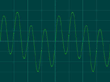
Added signals
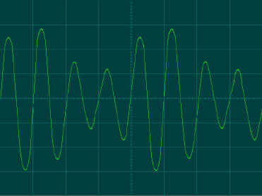
Mixed signals
When this is done, something happens: The two original signal frequencies are still in the resultant signal, but two more are created, the sum frequency and the difference frequency. So if we mix a 1000kc signal with a 1455kc signal, we get two new signals; 455kc and 2455kc.
Frequency conversion
This means that we can convert the frequency of any signal into the right frequency. So all we have to do is build a tuned amplifier with a fixed frequency, then convert the signals we want to receive so they can pass through it. If we build a local oscillator with a variable frequency, feed its signal to a mixer stage together with the antenna signal, and feed the result through our tuned amplifier, then whatever signal hits the right converted frequency (we call this the intermidiate frequency, or IF), that will be the signal we receive. All we need more is a detector and an audio amplifier.
Wait! Take the example above: We wanted to receive 1000kc, so we made an oscillator signal of 1455kc and got an IF of 455kc (this is a very commonly used IF frequency). That is all very well, but what if there is another station at 1910kc? We are going to receive that too, because it will also produce 455kc! This is called the mirror frequency or just mirror (US terminology has this as the IMAGE frequency, but here, we'll stick to mirror). We have to add a tuned circuit at the input to prevent the mirror to enter the mixer. This is called a preselector, and it has to be variable, tracking the oscillator, but because the frequencies are quite far apart, this is no big deal, a simple LC circuit with a two-gang variable capacitor (the other controlling the oscillator) will do. So now we are ready to draw a simple schematic diagram of our receiver:
This is our superheterodyne receiver. Heterodyne is the name of the tones or new frequencies that come from mixing two signals, and super comes from the fact that these frequencies are above the audible spectrum. "Super" being one of the buzzwords of the first part of the twentieth century, imagine the radio salesmen's bliss when they could quite honestly tell their customers that the radio they were selling was "a Super".
Lets look at a few details
In the following, we will examine the superheterodyne receiver in more detail. The superheterodyne principle is still almost totally predominant in receiver technology, but we use early AM radio tube circuits here. Note that this is a simplified scematic, various parts not essential to the signal threatment are omitted, others that may have double functions in a real radio are shown seperate. If you study real schematics, you will find that most older tube radios are built very much alike. This also means that it is quite feasible to work with and repair an old tube radio, even if you dont happen to have a schematic for that particular model.
Starting from left, we have the input tuned circuit. The antenna is coupled to it via a coil wound together with L1. Together with C1, L1 forms the tuned circuit that gives us our mirror selectivity. The received signal is fed to the control grid of V1, which works as an RF amplifier. V1 has other duties, however: A multiple grid tube (heptode), V1 also functions as a mixer. Grid 3 is an extra control grid (the purposes of the remaining grids will not be discussed here), and to this is fed the signal from our local oscillator.
V2 forms the local oscillator. The signal from the anode is fed back to the grid through the tuned circuit C2/L2. This is the circuit that determines the oscillator frequency and thus the exact station to receive. The two variable capacitors, C1 and C2 are mounted together on the same axis and move together, making the two tuned circuits track (actually, there is a bit more to making them track well, but that's another story).
So, according to the theory discussed above, we should have 4 signals present at the anode of V1: The oscillator frequency, the received frequency, the sum of those two, and the difference between them. It is the difference frequency we are interested in, so the signal is sent to a tuned circuit, C3/L3. Critically coupled to C3/L3 is another tuned circuit, C4/L4. Together, they form a band-pass filter, letting the IF band pass through.
But this is not quite good enough. We need more amplification, and we need better band-pass characteristics. V3 forms an amplifier, and the next set of tuned circuits, C5/L5 and C6/L6, complete our IF amplifier. The circuits in the IF amplifier have to be carefully tuned to get the right characteristics, but this needs to be done only once, at the manufacturer; when the radio is in use, all received frequencies are converted to fit the IF amplifier.
Finally, we need a detector V4, which rectifies the signal, extracting the AF part, and an audio amplifier, V5 and V6. R1 is the volume control.
Hans Egebo