Vacuum tube biasing methods
This article describes the most common methods of obtaining negative bias voltages in vaccum tube circuits.
Prerequisite: General knowledge of vacuum tubes, like from my article What's Inside Vacuum Tubes.
OK, now say all the jokes you want about this article being biased. ------ Thank you, - and on with the text:
General
In most configurations, the vacuum tubes need a negative bias on the control grid, grid 1. The reason for this is that the tube characteristics change drastically if the control grid becomes positive: A grid current will flow, and the amplification and transfer characteristics will change. So most tubes are built for an operating range with a negative grid bias of several volts. This means that our equipment really needs three supply voltages: A low voltage for filament power (possibly AC), a positive voltage (B+) in the order of 50-350V for plate power, and a negative voltage (B-) in the order of 6-20V for grid bias. Many battery sets actually use a separate battery for this; direct heated battery tubes will need to have their cathodes wired to the same potential, and as the bias current consumption is very low, the extra battery is not too costly.
In mains powered sets, the problem is different: To make an extra voltage supply, even a low current one, you need an extra rectifier and an extra filter, possibly an extra transformer winding. To avoid this complication, several alternative methods have been used to obtain bias.
Self biasing stage
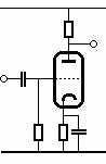
An obvious way to get a negative bias without having a negative supply is to put a positive voltage on the cathode; the tube will now "see" a negative bias. And the simplest way to do that is to insert a resistor in series with the cathode. The current flowing through the tube will now create a voltage drop over the resistor and with the grid referenced to zero, the tube will be properly biased.
Assume a tube needs -4V on the grid for 10mA of plate current, then we need to insert a 4KOhm resistor in the chatode circuit (nearest standard value: 3.9K). The smart thing is that this voltage is self-regulating: If the tube is built to draw 10mA with a -4V bias, thats exactly the voltage we will get. The proper bias for various plate currents can be looked up in tube data sheets. Note the decoupling capacitor: As the signal makes the anode current swing, the bias will swing with it and provide a negative feed-back, effectively limiting the amplification in the stage to the ratio between the cathode resistor and the plate resistor. This will make for a very fine linearity, but if we want higher amplification, we need to decouple the cathode by placing a capacitor across the cathode resistor as shown. Self-biasing is very useful in AF amplifiers and other amplifier stages without AGC.
In radio receivers, the stages that are AGC regulated pose a problem: The AGC introduces an extra bias regulation and a self-biasing stage would counteract this regulation, making the AGC less effective. Therefore, such stages are usually supplied with some kind of external bias.
Lifted cathode
One way of implementing an external bias to a stage is to 'lift' the cathode by connecting it to some suitable positive voltage. Usually this will be the cathode of the self-biasing output stage. The output stage draws a high current compared to e.g. an IF amplifier, so in effect, this can be used as a positive voltage source.
One drawback of this configuration is that it can complicate trouble-shooting: A fault in the AF output may cause the IF amplifier to act strange, so the technician must be careful when interpreting symptoms. Another drawback is complexity: Note that since the IF stage usually requires less bias than the output stage, a voltage divider is needed and the cathode has to be decoupled with a capacitor. If several stages are to be biased this way, things become complicated, and since what we are really doing is to establish a raised zero reference, we might as well go all the way and use a:
Power supply backoff
Suppose we insert a resistor in the negative lead of our power supply. The entire B+ current consumption of the set will run through it and create a voltage drop. If we connect our chassis to the positive end of the resistor, the end towards the power supply will be negative when measured from the equipment ground:
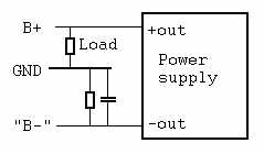
Here the drawing has been made to show the principle very clearly, but in real life schematics, this construction tends to look rather obscure and can give many headaches if you dont spot it for what it is. Let's first see the position of the resistor in the three power supplies discussed in another article:
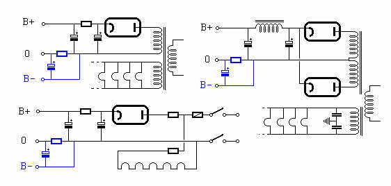
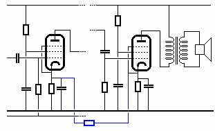
Note that the resistor has to be decoupled since the current drawn by the set will vary with the signal. Now, all cathodes in the set can be connected directly to chassis, and the various biases can be made by suitable voltage dividers. The great difference is that we are now at grid level, so currents are small and mostly decoupling is not needed. Here is the receiver from the Superheterodyne article with the backoff supply principle implemented.
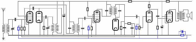
An additional advantage for this scheme is that many of double tubes used in real sets have common cathodes. So being able to wire them all to chassis makes the design simpler.
Note that with the backoff biasing scheme, the filter capacitors do NOT have their negative sides connected to chassis. If they get connected to chassis, either by a short circuit or by mistake when replacing them, the entire set will be without bias! The unbiased output stage will draw a lot of current, so if you have replaced the filter capacitors of a radio and the rectifier tube becomes red-hot, look for this error.
Grid current bias
One more type of bias is common, but not so much in receivers, although the local oscillator may use it: The signal can be used to create the bias:
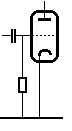
Looks simple, doesn't it? What happens is that every time the signal swings positive, the grid acts like the plate of a diode: A current runs between the cathode and the grid charging the coupling capacitor. The capacitor is slowly discharged through the grid resistor, and the DC voltage across it supplies the negative bias. There is some AGC effect in this because a larger signal will provide a more negative bias, but the transition into the positive region will cause some signal distortion, so it can only be used in stages that dont have to be linear, which mainly means tuned RF amplifiers and oscillators. The scheme is widely used in transmitters where it is quite common to tune one stage to maximum negative bias in the next one. Especially frequency multiplier stages work well in this way, because the inherent unlinearity is an asset here. Also grid-dip meters work in this fashion. And if you look at the receiver schematic above, you will notice that the oscillator uses this kind of bias.
Separate bias supply
Finally, it must be mentioned that in some equipment you will actually find a separate negative supply for bias. For the cost of the extra components, this gives a much more straight-forward situation, and in equipment where the current consumption will vary considerably during normal use or where DC-coupled amplifiers are used, a proper bias supply is almost a neccessity.
Hans Egebo