What's inside vacuum Tubes?
An introduction to basic tube technology
It started with the incandescent lamp. During the early experiments with incandescent lamps, it was discovered that under the right circumstances, a vacuum could conduct electricity. What happens is that the hot filament emits electrons into the vacuum around it. If there was only the filament there, that would be it; those electrons would hover in a cloud around the filament, balanced between their mutual repellant forces and the relative attraction of the neutral filament. But if we introduce an additional electrode and apply a positive voltage to it, the electrons will accelerate across the gap through the vacuum and impact on the positive electrode; a current flows. If we apply a negative voltage to the cold electrode, no current flows, because the cold surface does not emit electrons. So now we have a component that allows current to pass only in one direction:
![]()
This is called a diode (which means something with two electrodes). The filament is called the cathode (generic name for a negative electrode), the other electrode is called the plate (because of its shape) or the anode (generic name for a positive electrode). Lets go through a few practical details while the tube itself is relatively simple:
Heater. As mentioned, the cathode must be hot to function, actually it must be red-hot. On early tubes, the cathode was simply a lamp-like filament, but there are many advantages in having the filament electrically separated from the actual cathode. One is that you can use AC to feed it, another is that it gives you greater freedom in the construction of equipment if you dont need to have all your cathodes wired together to a common filament supply. The solution is indirect heating; the cathode is a thin pipe with the filament inside but electrically isolated from the cathode. On the schematic, it looks like this:
![]()
On most schematics, you will se filaments drawn separately somewhere outside the other circuitry, this makes for a much more readable schematic. There are two draw-backs of indirect heating. One is that the tube needs some warm-up time, the other is that it takes more power. The latter is the reason why direct heating stayed in use in battery radios till the very end.
For most of the rest of this article, we will ignore the filament and just draw the cathode.
Tubes become active
The diode tube had not been in existence for long before a third electrode was introduced. If a grid was placed between the cathode and the plate, it was found that a negative voltage on this grid would reduce the flow of electrons because some of them were repelled by the negative grid. A sufficiently negative voltage will stop the current altogether, this is called the cut-off voltage. As the grid is placed closer to the cathode than the plate, the voltage on the grid has more influence on the electron current than the voltage on the plate. This means that a given change in grid voltage can give rise to a larger change in plate voltage: We have an amplifier!
![]()
This device is called a triode (meaning three electrodes). The triode was predominant through the first decade or so of the childhood of radio technology. To understand why it was later relegated to a secondary role in most areas, we need to look at some technicalities. The triode basically acts as a variable resistor, it resistance being determined by the grid bias. This is not surprising; the electrical field from the plate draws a current by attracting the electrons emitted from the cathode. The stronger the field, the stronger the current. The grid bias modifies the field and determines the effective resistance of the tube.
The resistive behaviour of the triode puts a limit to the amplification you can get from it. Consider this: If the grid signal reduces the current flowing in the triode, the plate voltage will rise (in all normal configurations), but the rising plate voltage will cause the tube to draw more current. Correspondingly, if the signal causes the triode to draw more current, the plate voltage will fall, again counteracting the signal. The tube has a built-in negative feed-back. Also, the plate and the grid function as the plates of a capacitor, we call this a parasitic capacitor, in effect connected between the grid and the plate. This capacitor is a few picofarads in value, and is of no importance in an AF amplifier, but in RF amplifiers, it can play havoc with the stability of the stage, especially tuned stages with LC circuits at both input and output will have a stong tendency to oscillate. In fact, an oscillator type has been constructed that uses the grid/plate capacity of a triode as feed-back path.
To overcome this effect, a second grid was introduced between the control grid and the plate. This is called the screen grid. It is connected to a positive voltage of the same order as the plate voltage. It not only screens the control grid from the plate and thus disconnects the parasitic internal capacity, but it also changes the characteristics of the tube from resistive to a constant current characteristic. More of this later, because the tetrode, as this tube is called (four electrodes), turns out to have some quirks that immidiately relegated it to a few special uses. What happens is that the positive screen grid accelerates the electrons going to the anode to a very high speed, and when they hit the plate, they sometimes knock loose electrons from the plate metal. This is called secondary emission, and the problem is that the electrical field from these loose electrons modifiy the current in the tube reducing it in an unwanted fashion. This meant that the tetrode was immidiately abandoned in favor of the pentode (tetrodes do live on as transmitter output tubes, where the secondary emission problem is overcome by other means). In the pentode, a third grid is introduced between the screen grid and the plate. This grid is held at the same potential as the cathode (in fact it is often internally connected to the cathode) and it repells the seconary emission electrons back into the plate.
![]()
This is the pentode. The pentode has good stability in a tuned amplifier and you will see that IF amplifiers are always built with pentodes. As mentioned, it also has different characteristics from the triode: Within the working area, the penthode almost acts as a constant current generator. This means that the potential voltage gain is higher. Are there no drawbacks? Well, apart from the more complex construction, there is noise. A grid causes noise in the signal and, obviously, three grids cause more noise. Also, the screen grid draws some current from B+. In the medium and short wave bands, the natural atmospheric noise floor is so high that it doesnt matter, but once we go into VHF and higher, pentodes are too noisy for input stages, and here triodes lived on to the very end. Also, the simplicity of triode stages ensured them a lasting role as AF preamplifiers.
But it didn't stop there
If you have looked at a receiver schematic, you will probably have noticed at least one tube with more than three grids. In superheterodyne receivers, you need a mixer stage, where the incoming signal is mixed with the local oscillator signal to produce an IF signal. Mixing can be accomplished by feeding the two signals to the same grid, but that means that the oscillator signal may also propagate to the input of the receiver and ultimately be transmitted from the antenna, and this may easily disturb other radios. To avoid this, tubes with two control grids were constructed, hexodes (six electrodes). To furter reduce the risk of coupling oscillator signal to the input, an additional grid can be used acting as a screen between the two control grids, making the tube a heptode (you guessed it: Seven electrodes). Of course, the noise problem mentioned above applies here; the five-grid heptode is rather noisy, and if the oscillator radiation problem can be addressed effectivly in other ways, mixer stage noise can be reduced by using a hexode.
Note the internally connected grids. In real life, the hexode or heptode will usually come as a double tube system together with a triode for the oscillator.
Finally, an octode exists and especially in radios from the thirties you will sometimes encounter this six-grid tube where two of the grids function as grid and plate for the oscillator forming a sort of integrated mixer-oscillator stage, but in later constructions the octode again became side-tracked, probably because of noise problems.
Physical construction
Early tubes were built much like their ancestors, the light-bulbs:
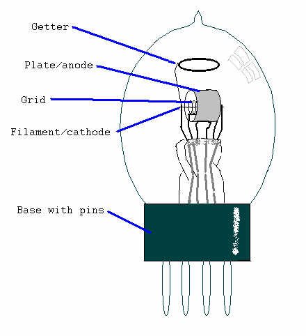
This is an old direct-heated triode tube. All the electrodes we already have discussed are plainly visible, but there is one more thing:
What is a getter?
Well, the glass enclosure that surrounds nearly all tubes (metal and ceramic enclosed tubes do exist) is evacuated; the air is pumped out leaving a vacuum. But no vacuum is perfect, some air will always remain. Air atoms will hinder the free movement of electrons inside the tube, but it is not too difficult to obtain a sufficiently good vacuum for the tube to function satisfactorily. Quite another problem is to ensure that it keeps functioning! The worst problem is the filament; even a low density of remaining oxygen in the tube will slowly but surely corrode away the hot filament. In a lightbulb, the hard vacuum is replaced by an inactive gas under low pressure, but that wouldnt do in a radio tube: The electrons would collide with the gas atoms. To make matters worse, glass is a silicon oxide compound; when it becomes hot, and tubes do tend to become hot, it will release oxygen atoms, and it will continue to do so during the entire lifetime of the tube. So something is needed that can absorb, get, the free oxygen atoms inside the tube, otherwise its lifetime will be deplorably short.
When you look at a normal radio tube, you will notice a metallic-looking area on the inside of the glass. This is the getter, and it is an easily oxydable metal, usually magnesium. When the tube is manufactured, the getter metal is placed on a ring- or frameshaped holder and after the glass enclosure has been evacuated and sealed, this ring is heated by induction. In normal air, it would burn like a miniature version of an old-fashioned photoflash, but in the almost total vacuum inside the tube, the magnesium evaporates and settles in an ultra-thin layer on the glass. Now, whenever a free oxygen atom (actually a molecule, O2, but thats irrelevant) comes by, it will form a magnesium oxide molecule and stay in the getter. This also means that you can get an impression of a tube's condition by looking at the getter: If the getter is grayish or white at the edges, the tube has seen better days. If the getter is all turned into a white powdery layer, the tube is air-filled and dead. Of course, a tube can have a perfectly healthy-looking getter and still be sick for other reasons.
Modern tube construction
By modern tubes I mean tubes from the forties and on, when both tube technology and -manufacturing techniques had matured.
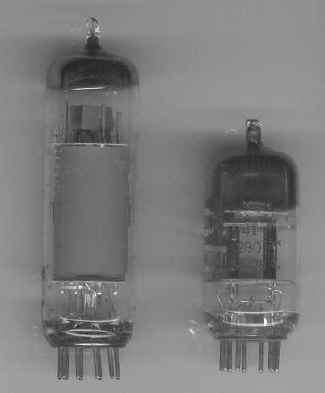
The picture shows a double triode and an output pentode. The various parts are held in place by two mica disks inside the cylindrical glass enclosure. As the production costs are nearly the same for a simple and a complicated tube, multiple function tubes are common, thus a typical four-tube set contains four physical tubes, one of which is the rectifier, but the receiver part really has six or seven tube functions: A triode/hexode for oscillator, another triode/hexode for IF and audio amplifiers, and a double diode/pentode for detector and audio output. Various other configurations are common too. There even existed a triode/double pentode; with this you could build an entire push-pull output stage, and a tape-recorder was actually manufactured with only this tube in it.
Vacuum tubes today
As I write this article, the year 2000 is drawing to an end, and semiconductors have reigned unchallenged over most old tube territories for the last thirty years, but vacuum tubes are far from dead yet. Actually, you are probably looking at one right now! Time IS running out for the cathode-ray tube, or picture tube, but because of its favorable price and excellent quality, it is likely to linger on for at least another decade. High-power RF applications is another area where tubes are still going strong. Some audio affectionados maintain that REAL audio amplifiers must be built with tubes. And nothing will ever replace the slight hum and warm sound and glow of a well-restored veteran radio set!
Hans Egebo