Vacuum Tube Amplifiers
This article covers commonly used vacuum tube amplifier configurations with emphasis on types used in veteran radios and veteran communication equipment. The article discusses each configuration first at a fairly elementary level, aimed at readers with limited technical insight or readers who just want an overview of the amplifier type. After this, some of the stages are discussed in more depth, to give readers who are interested in this a deeper knowledge of how the stage is built and dimensioned. For a general overview, these parts, which are in blue, can be skipped.
Prerequisite: The reader should have basic knowledge of superheterodyne concepts, vacuum tube technology, and biasing methods.
The vacuum tube as amplifier
All tube types except diodes have the potential to work as amplifiers. A voltage change on the control grid will cause a corresponding change in the plate current, so basically, the tube is a voltage amplifier, but the input voltage signal is changed to a current signal. The trick when building an amplifier is then to utilize this current signal in a suitable way, either by using it directly or by changing it back to a voltage signal.
Early methods
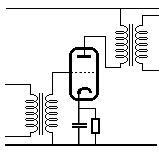
The first tube amplifiers used transformer coupling. A transformer basically handles current, so by letting the plate current pass through a transformer, you utilize the current signal very well.

Another advantage of the transformer is that the winding ratio can be made to adapt the signal to the next stage; if the next is to be another amplifier tube, the transformer can be a step-up transformer, effectively giving up to 10 times extra gain (higher ratios tend to run into various practical problems). If the next "stage" is a loudspeaker, on the other hand, a step-down transformer can be used, matching the low impedance of the loudspeaker. Once radio technology came out of infancy, tubes became better and cheaper, so in AF amplifiers, the transformer coupling only lived on in the output stage, where low impedance loudspeakers would otherwise have been difficult to drive with the relatively high-impedanced vacuum tube. In RF amplifiers, transformers are simple and cheap and not only have they stayed the tube era out, but they live on in even the most modern solid state circuits. We will return RF amplifiers later.
Resistance coupling
Transformers for AF are bulky and expensive, so as the gain-factor of tubes became better, the resistor coupling became the method of choice for most AF amplifiers and even some RF amplifiers. A resistor is inserted in the plate circuit instead of the transformer. As the grid signal changes the plate current, obviously, the voltage drop over the plate resistor will change accordingly, giving raise to a voltage signal on the plate. This signal will be in opposite phase compared to the grid signal; when the grid signal voltage swings in the negative direction, the plate current will fall, thus the voltage drop over the plate resistor will be smaller, making the plate voltage rise, whereas a positive grid swing will increase the plate current and lower the plate voltage.
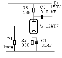
The plate signal will have a rather large DC component: It will swing around an average plate voltage, typically at around two thirds of the B+ voltage. To keep this voltage from entering the next stage, we use a coupling capacitor, or in older terminology, a blocking capacitor (because it blocks the DC, but lets the signal pass). Obviously, unpleasant side effects may occur if this capacitor fails and shorts out, especially if the next stage is a transformer coupled output stage: The output tube will get a positive bias making it draw an extreme amount of plate current, which may in turn overload and damage or destroy any or all of the following parts: Output tube, output transformer, rectifier tube(s), mains transformer. Some restorers of old radios for this reason prefer to replace all coupling capacitors as a preventive measure.
A look at the details
The values in the schematic are for a
stage using ½ 12AT7 (ECC81). At 100V plate voltage, this tube will draw 3mA plate current
with a grid bias of -1V, so to make the stage autobiasing, we need a cathode resistor R2
of 330 ohms. The decoupling capacitor C1 needs to have an impedance comparable to R2 at
the low frequency limit, lets say at 20Hz, thats
1 / 2p *300 * 20 ~
33MF (so this will be an electrolytic). The grid return resistor R1 is there because
electrons leaving the cathode will occasionally hit the grid and if they are not led away
from the grid, a negative charge will accumulate, eventually cutting off the plate
current. This resistor just needs to be some large value, usually 1meg is used. The plate
resistor R3: The setup with the bias used calls for the tube to have a plate voltage of
100V, and if we assume a B+ of 150V, this means that the voltage across R3 must be 50V,
and at 3mA, that gives us 17k (standard value: 18k). A configuration like this, with about
1/3 of the B+ across the resistor will give a near optimum signal swing (when saturated, a
vacuum tube has a considerable voltage drop over it, so a 100V swing is all we can hope
for). Finally, the coupling capacitor C2 needs to have a low impedance compared to the
input resistance of the next stage at the low frequency limit. Assuming 1meg and 20Hz, we
get 0.01MF (easily within polyester range).
So, what gain can we expect from this stage? The conductance for the 12AT7 at this bias point is 5.5mA/V, so a 1V signal will ideally give a 5.5mA change in plate current. We might expect this to result in a 99V signal across the 18k, but life is not like that: A triode basically acts like a resistor with its value controlled by the grid. If this were an ideal resistor, we would expect it to be 100/3=33k, but the plate voltage has an influence on the resistance of the tube, so the dynamic impedance of the tube is only 16.5k (according to the data sheet). This impedance has to be calculated in parallel with the 18k plate resistor, giving 1/(1/18+1/16.5)=8.6k, so the actual voltage swing on the plate will be 8.6*3=26V, giving our stage a voltage gain of 26. Then there is the load of the next stage, but 1meg load will not make a world of difference.
Output stage
As I mentioned, one place the transformer coupling has stayed in use is in AF output stages. The signal impedance of even a powerful output tube is still in the kiloohms range, but loudspeakers typically have impedances of 4-8 ohms. The transformer is perfect for this, and at the same time provides for a safe isolation between the voltages inside the set and outside circuits like external speakers.
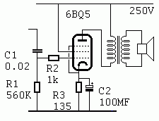
Above is a full diagram of a typical single-tube output stage cabable of delivering 5-6 watts of output power. Here, as mentioned, the transformer is virtually indispensable. A stage like this is biased for a quiescent current of half the full swing; this is called class A, a naming convention that has led some people to assume that such a stage is in some way better than a stage that runs in class B (discussed later in this article). We find another electrolytic here, again at the cathode resistor. If this capacitor shorts out, the stage will draw a lot of current, possibly with the effects described earlier, but the more common fault for an old electrolytic is that it dries out and looses most of its capacity. In this case, a negative feed-back occurs over the cathode resistor, which will reduce the amplification in the stage considerably, probably resulting in a low output volume.
A look at the details
Let's start at the input: The grid return resistor R1 is empirically set to 560k (a big grid produces more return current), so the coupling capacitor C1 ends at 0.02MF. R2 is there to prevent high frequency oscillation (in spite being built for AF, this tube will work well into the shortwave band), the 1k value is again empirical. The cathode resistor R3 is 135ohms to give us a -6.5V bias at 48mA, this leaves C2 at 100MF. The output impedance of the stage with this bias is 5.2k. This value is equivalent to the load value we calculated for the triode stage (internal resistance in parallel with an imaginary plate resistor), and gives an output power of 5.7W, according to the data sheet. If the speaker impedance is 8ohms, the winding ratio of the transformer is the square root of the impedance ratio: 26.
With no signal, the full B+ (250V) will be at the plate since the DC resistance of the transformer is low (in the order of 200ohms). 5.7W in 5.2k is 172V RMS, 243V peak, so with a positive signal swing at the grid the plate voltage swings very low, but what with a negative grid signal? Well, the plate current will now start to fall from the 48mA, but the inductance of the transformer will make the plate voltage rise above B+ to nearly 500V, so the full voltage swing at the plate is a teoretical 500V PP! Whether the tube is actually able to swing down to a few volts is perhaps doubtfull, but th upward swing is a real thing, and now watch out: If the load is larger than 8ohms, as when the speaker is open, the voltage will simply rise till the power can be dissipated SOMEWHERE. I have seen the output transformer of a 2W amplifier arch to the iron core of the transformer. So contrary to what you might expect, underloading can be more damaging to this stage than overloading. An overload, like a 4ohms speaker, will just reduce the voltage swing at the plate, and we won't get optimal power, but no damage will be done. If the amplifier is built with a high negative feed-back, the situation can be different.
More power
If we want more power, we could use a bigger tube, but the quiescent DC current in the class A stage poses some problems: To cope with the DC magnetization, the transformer has to have a relatively large core; in effect, we only use half the operating range of the transformer core, since it is only ever magnetized in one direction. Also, the power stage always draws power equivalent to full output, and this is really ineffective, since even if we run it at full volume, the average output power in music or speach will be considerably lower than the sound peaks. So a big amplifier will dissipate a lot of unneccessary heat. Instead, we can choose to run two tubes in a so-called push-pull stage, where each tube takes care of one half of the signal:
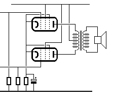
Right away, you might expect this stage to be able to handle twice the power than the one above, but because the two 6BQ5 tubes dont need to negotiate the high quiescent current, they are actually able to deliver up to 17W. Note the center tab on the output transformer: Not only is the quiescent current lower, but the bias current to the two tubes cancel each other out in the transformer. As a result, the transformer for our 17W amplifier need not be much larger physically than the one for the 5W class A stage. This class is called a class B stage, signifying that the quiescent current is at a level considerably lower than the mean signal bias. The tubes need two input signals, in opposite phase, so there has to be a driver stage that supplies this. There are several methods of doing this, they are discussed below.
Details
The obvious way to get a split-phase signal is of course to use a transformer:
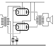
This kind of construction can be seen in old sets, but again, transformers are relatively expensive, and also their frequency transfer charateristics are less than ideal, so there are good reasons to try and avoid them if possible. Interestingly, this configuration later had a revival: Transistor output stages used it extensively during the first 15 years or so of transistor radios. But for tube sets, other methods came in use. Some amplifiers use a simple phase splitter stage:
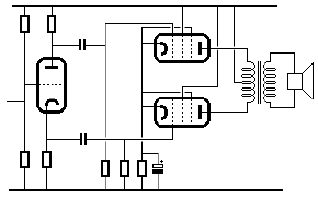
The cathode- and plate resistors are the same value, so equal signals, but in opposite phase, are found on cathode and plate. Note the voltage divider to the grid: Since the cathode resistor is far larger than in a normal self-biasing stage, the grid must be "lifted" to obtain a suitable bias. There is no overall gain in the stage, so a previous stage is usually needed to provide the neccessary gain. Also, as the output impedances of the two outputs are different, some imbalance can occur, especially at the extreme ends of the frequency range. This next driver construction, while slightly more complex, is better balanced:
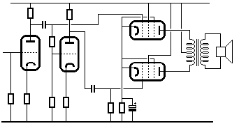
The idea is simple; one stage is a normal amplifier, the next one is too, but a voltage divider at the input lowers the signal back to the level before the first stage, then it is amplified back up, and the phase is inverted. Note that the stages have no decoupling on the cathode resistors: This gives us precise control of the gain which will simply be equal to the ratio between the cathode resistor and the plate resistor.
Finally, the cheapie:
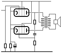
The idea is, of course, that if we feed signal to one output tube, there will be a nice inverted signal on its plate, which can then be fed to the other tube. This stage is inherently poorly balanced, because if tube no. 2 gets too much signal, the stage will oscillate, so to be on the safe side it has to be underbalanced. Obviously, the only advantage of this configuration is its simplicity, and it is probably quite rare, but does exist.
Bias considerations
As mentioned, the bias conditions for push-pull stages are normally called class B, but most tube amplifiers really run in what modern amplifier designers would classify as AB. The reason is that the bias is fairly high compared to class B solid state stages. This means that cross-over distortion is not too big a problem, but it is also a product of neccessity: Normally, the stage will be self-biasing, so to back the quiescent current way off, you would need a quite large cathode resistor, so the normal 15-30W radio or HI-FI output stage will run with a bias current of about 25% of max current. If bias is to be lowered to the 2-5% level of modern amplifiers, a negative supply is normally needed.
RF amplifiers
One type of RF amplifier found in nearly any receiver is the IF amplifier:
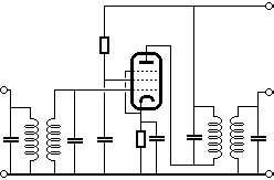
Obviously, this is really a transformer coupled stage. RF transformers are simpler and cheaper than their AF counterparts because they have fewer windings and the bulky iron core can be replaced by ferrite cores or nothing at all. Also, most RF amplifiers are tuned, so the transformer coil naturally becomes part of the tuned circuit. Note that a pentode is used: In a triode, the internal capacity between the grid and the plate acts as a parasitic feed-back path, and because of the phase transitions around the resonant frequency of the tuned circuits, the stage will have a strong tendency to oscillate. The screen-grid in the pentode disconnects this capacity, and makes the stage inherently stable.
At high frequencies, pentodes become a problem. Not only do they have a higher noise level than triodes, but the more complex tube system has to be physically larger, and this limits their performance at high frequencies. So here we are stuck with the triode, and the inherent instability if the triode stage must be overcome in another way. Take a look at this:
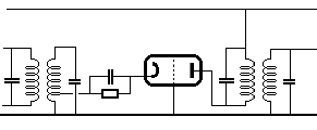
This configuration is called grounded grid, for obvious reasons. What controls the plate current is the cathode-grid voltage, so instead of holding the cathode at a fixed voltage (effectively grounding it) and feeding the signal to the grid, it is possible to ground the grid and feed the signal to the cathode. The grounded grid effectively screens the plate from the signal input, which is now the cathode, and thus the stability is vastly improved. The draw-back is that the stage has a low input impedance, but since we are using a transformer coupling this is not too big a problem. The impedance matching in the stage shown is achieved by feeding the stage from a tab on the input coil. The grounded grid configuration is widely used for RF stages at all frequencies above some 50mHz. For the real high frequencies, special triodes exist that can work effectively well into the gigahertz range.
The low input impedance makes the grounded grid configuration unfit for AF amplifiers, except for the special uses, where the low input impedance is desireable, like dynamic microphone inputs, etc. To get the best of both worlds, the cascode configuration can be used:
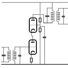
This set up, at the expence of an extra triode system, has the high input impedance of the grounded cathode stage, an excellent input-output separation, and a high gain, making it very well suited for tuned amplifier stages. It is rare in commercial receivers, not only because of its complexity, but also because it is difficult to AGC regulate.
Special amplifiers
We have looked now at two basic amplifier couplings, grounded cathode, and grounded grid. A third exists: Grounded plate:
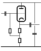
As you can see, the plate is of course connected to B+, not to ground, but signal-wise, B+ and ground are the same (to signify this, one of the B+ filter or decoupling capacitors is shown), so what happens is that no signal occurs at the plate, instead the signal is taken from the cathode. The max voltage gain from this stage is 1, but it has a high current gain, or, in other words, it has a low output impedance. The output impedance is much lower than the cathode resistor, because a high negative feed-back exists within the stage. Any change in output voltage because of a load will change the cathode-grid voltage and be countered by a current change, so the output impedance equals the cathode resistor divided by the gain factor of the tube. The input impedance, on the other hand, is very high: The grid return resistor may be 1meg, but it is not referenced to ground, it is referenced to a point close to the cathode, where there is almost the same signal as on the input. Therefore the input impedance is equal to the grid resistor multiplied with the ratio between the two cathode resistors, if we assume it is in this case 10, it will give us an input impedance of 10megs. More sophisticated input back-off or bootstrap schemes can be employed taking the input impedance into hundreds of megs. The grounded plate, or cathode follower circuit is used whereever you need a high input impedance and/or a low output impedance.
We can couple a cathode to another and get this, the differential amplifier:
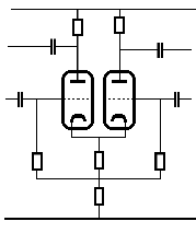
The circuit has here been drawn symmetrical, and what really happens is that the two tubes divide the current from the cathode resistor between them. At small signal levels, this current can be considered constant, which means that what really gets amplified is the difference between the two grids. Plate signals are in opposite phase. The signal between the two grids is called the differential mode signal, any signal that is the same on both grids is called common mode, and common mode signals are suppressed, how much depends on how well the stage is balanced and on how close the cathode current is to a constant current. The differential amplifier has high input impedances and can have medium to high gain. The circuit is mainly used in instrument circuits, but can also be seen as driver for push-pull output stages.
Finally, still mainly for instumentation purposes, DC coupling
These days, complementary solid state devices have made construction of DC coupled amplifiers a breeze, actually most solid state AF amplifiers are largely DC coupled, if only to save capacitors, but back in the tube era, getting that zero hertz lower frequency limit was a rather complex undertaking. Here is a simple two-stage DC amplifier:
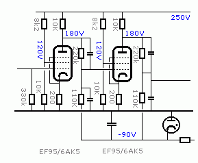
There is really no getting around a B- supply here, and since the signal partly refers to B-, it has to be a good one, so often stabilizing tubes are used. I have assumed a -90V B- here, as it can easily be stabilized with a neon lamp. The trick about it all is the voltage divider, which gets us back to an appropriate level for the second stage. This of course costs us some gain, as the signal is also divided. The capacitors around the voltage dividers are there to compensate for various stray capacities, most prominently the cathode-grid capacity of the second tube, which would otherwise form a low-pass filter together with the resistirs, and lower the upper frequency limit considerably. The capacitors are quite small, in the MMF range and basically inversely proportional to the resistors, but the exact values will have to be determined empirically, because of the influence of stray capacities. Properly built, this amplifier will be linear from DC to over a megahertz. The method of transferring a DC signal by means of a voltage divider to a negative supply can be applied to most amplifier configurations.
There are quite a few interesting details: We are using pentodes, because they have better gain potential than triodes. The first tube is auto-biasing, this allows us to have the grid at zero potential. The cathode resistor is of course not decoupled, since we cannot decouple for DC, anyway we want control over the gain and we want the linearity from the negative feed-back it offers. The next tube also has a cathode resistor although we could easily bias that via the voltage divider that transfers the signal, but we also want the negative feed-back here. The screen grids need 120V for the bias point we are using; to get that from 250V, we would normally just fit a 56k resistor, which would get us close enough with the 2.4mA drawn by the grid, but as the screen grid cannot be decoupled, our gain would be reduced, so we need to add some stabilizing. A really expensive amplifier would have a separate B+ for this, but here we just use a voltage divider with some extra current running through it to get a more stable screen grid voltage. In a real application, some bias adjustment would be needed to trim away the DC offset that will invariably occur. This amplifier has a total gain in excess of 250, and some negative feed-back might be employed to improve linearity and frequency range.
Hans Egebo